Scaler
This shield and its corresponding sketch is designed as a simple and
low-cost scaler for high-energy physics physics application, e.g.,
reading out of signals from photomultiplier tubes in counting mode.
The shield is supposed to operate with the sketch
Evolving version
- Production files: Fritzing file
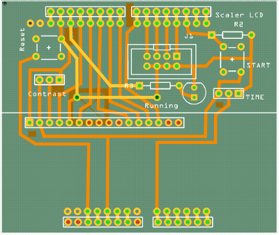
Features
It is a first prototype of a 4-channel scaler with LCD to display the resulting counts. When the START button is pressed, arduino begins counting the number of low-to-high transitions from the 4 inputs in the J1 connector for a fixed amount of time. This integration time is always displayed in the LCD and can be changed by varying the resistance of the potentiometer TIME. After the integration time expires, the counts are displayed in the 4 rows of the LCD. A run number is also stored and displayed in the LCD, it is incremented every time the START button is pressed. No connection with a PC is required (except for loading the sketch of course) since all the information are displayed on the LCD.
J1 is a generic 8-pin connector for the input signals. The 4 upper pins are directly connected to Arduino input pins. The 4 lower pins set to ground to provide a reference voltage.
A Running LED is added to show the system status. It turns on as the system starts counting.
A hit is recorded by continuously (i.e. every 4 us) reading the status of the input pins and looking for low-to-high transitions, i.e., high in current readout and low in previous readout (this is appropriate only in low counting rate regime).