interface Module
- class interface.Interface(timeout=1.0, **kwargs)[source]
Bases: object
Communications library.
This class contains methods that can be used to interact with the vLabtool
Initialization does the following
- connects to tty device
- loads calibration values.
Arguments Description timeout serial port read timeout. default = 1s >>> from vLabtool import interface >>> I = interface.Interface(2.0) >>> print I <interface.Interface instance at 0xb6c0cac>
Once you have instantiated this class, its various methods will allow access to all the features built into the device.
- I2C = None
Sub-Instance I2C of the Interface library contains methods to access devices connected to the I2C port.
- example::
>>> I.I2C.start(self.ADDRESS,0) #writing mode
>>> I.I2C.send(0x01)
>>> I.I2C.stop()
See also
I2C for complete documentation
- SPI = None
Sub-Instance SPI of the Interface library contains methods to access devices connected to the SPI port.
- example::
>>> I=Interface()
>>> I.SPI.start('CS1')
>>> I.SPI.send16(0xAAFF)
>>> print I.SPI.send16(0xFFFF)
some number
See also
SPI for complete documentation
- NRF = None
Sub-Instance NRF of the Interface library contains methods to access wireless sensor nodes via an NRF24L01+ module connnected to the SPI port
try out the wireless modules app by running vLabtool-experiments from the command line.
- example::
>>> I=interface.Interface()
>>> I.NRF.start_token_manager()  #Start listening to any nodes that may turn on
>>> while 1:   #Wait for at least one node to register itself
>>>     lst = I.NRF.get_nodelist()
>>>     print lst
>>>     time.sleep(0.5)
>>>     if(len(lst)>0):break
>>> I.NRF.stop_token_manager()  # Registrations closed!
>>> LINK = I.newRadioLink(address=lst.keys()[0])  #lst = dictionary with node addresses as keys, and I2C sensors as values
>>> print LINK.I2C_scan()                                                 #vLabtool automatically transmits stuff to LINK's address, and retrieves sensor info.
See also
NRF24L01 for complete documentation
- newRadioLink(**args)[source]
Arguments **Kwargs address - address of the node. a 24 bit number. Printed on the nodes. Can also be retrieved using
- get_nodelist
Returns: RadioLink See also
- reconnect()[source]
Attempts to reconnect to the device in case of a commmunication error or accidental disconnect.
- capture1(ch, ns, tg)[source]
Blocking call that fetches an oscilloscope trace from the specified input channel
Arguments ch Channel to select as input. [‘CH1’..’CH9’,‘5V’,’PCS’,‘9V’,’IN1’,’SEN’] ns Number of samples to fetch. Maximum 10000 tg Timegap between samples in microseconds 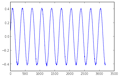
A sine wave captured and plotted.
Example
>>> from pylab import *
>>> from Labtools import interface
>>> I=interface.Interface()
>>> x,y = I.capture1('CH1',3200,1)
>>> plot(x,y)
>>> show()
Returns: Arrays X(timestamps),Y(Corresponding Voltage values)
- capture2(ns, tg)[source]
Blocking call that fetches oscilloscope traces from CH1,CH2
Arguments ns Number of samples to fetch. Maximum 5000 tg Timegap between samples in microseconds 
Two sine waves captured and plotted.
Example
>>> from pylab import *
>>> from Labtools import interface
>>> I=interface.Interface()
>>> x,y1,y2 = I.capture2(1600,1.25)
>>> plot(x,y1)
>>> plot(x,y2)
>>> show()
Returns: Arrays X(timestamps),Y1(Voltage at CH1),Y2(Voltage at CH2)
- capture4(ns, tg)[source]
Blocking call that fetches oscilloscope traces from CH1,CH2,CH3,CH4
Arguments ns Number of samples to fetch. Maximum 2500 tg Timegap between samples in microseconds. Minimum 1.75uS 
Four traces captured and plotted.
Example
>>> from pylab import *
>>> I=interface.Interface()
>>> x,y1,y2,y3,y4 = I.capture4(800,1.75)
>>> plot(x,y1)
>>> plot(x,y2)
>>> plot(x,y3)
>>> plot(x,y4)
>>> show()
Returns: Arrays X(timestamps),Y1(Voltage at CH1),Y2(Voltage at CH2),Y3(Voltage at CH3),Y4(Voltage at CH4)
- capture_traces(num, samples, tg, channel_one_input='CH1', CH123SA=0, **kwargs)[source]
Instruct the ADC to start sampling. use fetch_trace to retrieve the data
Arguments num Channels to acquire. 1/2/4 samples Total points to store per channel. Maximum 3200 total. tg Timegap between two successive samples (in uSec) channel_one_input map channel 1 to ‘CH1’ ... ‘CH9’ **kwargs - trigger
Whether or not to trigger the oscilloscope based on the voltage level set by configure_trigger 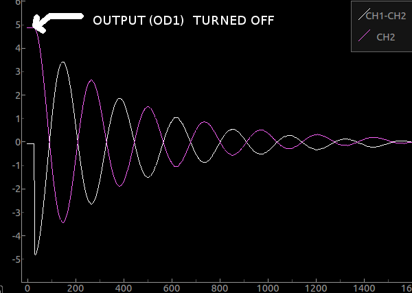
Transient response of an Inductor and Capacitor in series
The following example demonstrates how to use this function to record active events.
- Connect a capacitor and an Inductor in series.
- Connect CH1 to the spare leg of the inductor. Also Connect OD1 to this point
- Connect CH2 to the junction between the capacitor and the inductor
- connect the spare leg of the capacitor to GND( ground )
- set OD1 initially high using set_state(OD1=1)
>>> I.set_state(OD1=1)  #Turn on OD1
>>> time.sleep(0.5)     #Arbitrary delay to wait for stabilization
>>> I.capture_traces(2,800,2,trigger=False)     #Start acquiring data (2 channels,800 samples, 2microsecond intervals)
>>> I.set_state(OD1=0)  #Turn off OD1. This must occur immediately after the previous line was executed.
>>> time.sleep(800*2*1e-6)      #Minimum interval to wait for completion of data acquisition. samples*timegap*(convert to Seconds)
>>> x,CH1=I.fetch_trace(1)
>>> x,CH2=I.fetch_trace(2)
>>> plot(x,CH1-CH2)     #Voltage across the inductor
>>> plot(x,CH2)         ##Voltage across the capacitor
>>> show()
The following events take place when the above snippet runs
- The oscilloscope starts storing voltages present at CH1 and CH2 every 2 microseconds
- The output OD1 was enabled, and this causes the voltage between the L and C to approach OD1 voltage. (It may or may not oscillate)
- The data from CH1 and CH2 was read into x,CH1,CH2
- Both traces were plotted in order to visualize the Transient response of series LC
Returns: nothing See also
fetch_trace , oscilloscope_progress , capture1 , capture2 , capture4
- capture_highres_traces(channel, samples, tg, **kwargs)[source]
Instruct the ADC to start sampling. use fetch_trace to retrieve the data
Arguments channel channel to acquire data from ‘CH1’ ... ‘CH9’ samples Total points to store per channel. Maximum 3200 total. tg Timegap between two successive samples (in uSec) **kwargs - trigger
Whether or not to trigger the oscilloscope based on the voltage level set by configure_trigger Returns: nothing See also
fetch_trace , oscilloscope_progress , capture1 , capture2 , capture4
- fetch_trace(channel_number)[source]
fetches a channel(1-4) captured by capture_traces called prior to this, and returns xaxis,yaxis
Arguments channel_number Any of the maximum of four channels that the oscilloscope captured. 1/2/3/4 Returns: time array,voltage array See also
- oscilloscope_progress()[source]
returns the number of samples acquired by the capture routines, and the conversion_done status
Returns: conversion done(bool) ,samples acquired (number) >>> I.start_capture(1,3200,2) >>> print I.oscilloscope_progress() (0,46) >>> time.sleep(3200*2e-6) >>> print I.oscilloscope_progress() (1,3200)
See also
- configure_trigger(chan, name, voltage, resolution=10)[source]
configure trigger parameters for 10-bit capture commands The capture routines will wait till a rising edge of the input signal crosses the specified level. The trigger will timeout within 8mS, and capture routines will start regardless.
These settings will not be used if the trigger option in the capture routines are set to False
Arguments chan channel . 0 or 1. corresponding to the channels being recorded by the capture routine(not the analog inputs) name the name of the channel. ‘CH1’... ‘V+’ voltage The voltage level that should trigger the capture sequence(in Volts) Example
>>> I.configure_trigger(0,1.1)
>>> I.capture_traces(4,800,2)
>>> I.fetch_trace(1)  #Unless a timeout occured, the first point of this channel will be close to 1.1Volts
>>> I.fetch_trace(2)  #This channel was acquired simultaneously with channel 1, so it's triggered along with the first
See also
- set_gain(channel, gain)[source]
set the gain of the selected PGA
Arguments channel ‘CH1’,’CH2’,’CH3’,’CH4’,’CH5’,’CH6’,’CH7’,’CH8’,’CH9’,‘5V’,’PCS’,‘9V’ gain (0-7) -> (1x,2x,4x,5x,8x,10x,16x,32x) Note
The gain value applied to a channel will result in better resolution for small amplitude signals.
However, values read using functions like get_average_voltage or capture_traces will not be 2x, or 4x times the input signal. These are calibrated to return accurate values of the original input signal.
>>> I.set_gain('CH1',7) #gain set to 32x on CH1
- get_average_voltage(channel_name, sleep=0)[source]
Return the voltage on the selected channel
Arguments Description channel_name ‘CH1’,’CH2’,’CH3’,’CH4’,’CH5’,’CH6’,’CH7’,’CH8’,’CH9’,‘5V’,’PCS’,‘9V’,’IN1’,’SEN’,’TEMP’ sleep read voltage in CPU sleep mode. not particularly useful. Also, Buggy. Example:
>>> print I.get_average_voltage('CH4')
1.002
- get_high_freq(pin)[source]
retrieves the frequency of the signal connected to ID1. >10MHz also good for lower frequencies, but avoid using it since the ADC cannot be used simultaneously. It shares a TIMER with the ADC.
The input frequency is fed to a 32 bit counter for a period of 100mS. The value of the counter at the end of 100mS is used to calculate the frequency.
See also
Arguments pin The input pin to measure frequency from. ‘ID1’ , ‘ID2’, ‘ID3’, ‘ID4’, ‘LMETER’,’CH4’ Returns: frequency
- get_freq(channel='ID1', timeout=0.1)[source]
Frequency measurement on IDx. Measures time taken for 16 rising edges of input signal. returns the frequency in Hertz
Arguments channel The input to measure frequency from. ‘ID1’ , ‘ID2’, ‘ID3’, ‘ID4’, ‘LMETER’,’CH4’ timeout This is a blocking call which will wait for one full wavelength before returning the calculated frequency. Use the timeout option if you’re unsure of the input signal. returns 0 if timed out Return float: frequency - connect SQR1 to ID1
>>> I.set_sqr1(2000,500,1) # TODO: edit this function
>>> print I.get_freq('ID1')
4000.0
>>> print I.r2r_time('ID1')     #time between successive rising edges
0.00025
>>> print I.f2f_time('ID1') #time between successive falling edges
0.00025
>>> print I.pulse_time('ID1') #may detect a low pulse, or a high pulse. Whichever comes first
6.25e-05
>>> I.duty_cycle('ID1')         #returns wavelength, high time
(0.00025,6.25e-05)
- r2r_time(channel='ID1', timeout=0.1)[source]
Returns the time interval between two rising edges of input signal on ID1
Arguments channel The input to measure time between two rising edges.’ID1’ , ‘ID2’, ‘ID3’, ‘ID4’, ‘LMETER’,’CH4’ timeout Use the timeout option if you’re unsure of the input signal time period. returns 0 if timed out Return float: time between two rising edges of input signal See also
- f2f_time(channel='ID1', timeout=0.1)[source]
Returns the time interval between two falling edges of input signal on ID1
Arguments channel The input to measure time between two falling edges. ‘ID1’ , ‘ID2’, ‘ID3’, ‘ID4’, ‘LMETER’,’CH4’ timeout Use the timeout option if you’re unsure of the input signal time period. returns 0 if timed out Return float: time between two falling edges of input signal See also
- DutyCycle(channel='ID1', timeout=0.1)[source]
duty cycle measurement on channel
returns wavelength(seconds), and length of first half of pulse(high time)
low time = (wavelength - high time)
Arguments channel The input pin to measure wavelength and high time. ‘ID1’ , ‘ID2’, ‘ID3’, ‘ID4’, ‘LMETER’,’CH4’ timeout Use the timeout option if you’re unsure of the input signal time period. returns 0 if timed out :return : wavelength,duty cycle
See also
- MeasureInterval(channel1, channel2, edge1, edge2, timeout=0.1)[source]
Measures time intervals between two logic level changes on any two digital inputs(both can be the same)
For example, one can measure the time interval between the occurence of a rising edge on ID1, and a falling edge on ID3. If the returned time is negative, it simply means that the event corresponding to channel2 occurred first.
returns the calculated time
Arguments channel1 The input pin to measure first logic level change channel1 - The input pin to measure second logic level change
- ‘ID1’ , ‘ID2’, ‘ID3’, ‘ID4’, ‘LMETER’,’CH4’
edge1 - The type of level change to detect in order to start the timer
- ‘rising’
- ‘falling’
- ‘four rising edges’
edge2 - The type of level change to detect in order to stop the timer
- ‘rising’
- ‘falling’
- ‘four rising edges’
timeout Use the timeout option if you’re unsure of the input signal time period. returns -1 if timed out :return : time
See also
- pulse_time(channel='CH1', timeout=0.1)[source]
pulse time measurement on ID1 returns pulse length(s) of high pulse or low pulse. whichever occurs first
Arguments channel - The input pin to measure pulse width from.
- ‘ID1’ , ‘ID2’, ‘ID3’, ‘ID4’, ‘LMETER’,’CH4’
timeout - Use the timeout option if you’re unsure of the input signal time period.
- returns 0 if timed out
Return float: pulse width in seconds See also
- setup_comparator(level=7, digital_filter=3)[source]
setup the voltage level and filtering on the analog comparator linked to CH4. It can then be used to directly estimate the frequency and other timing details of input analog waveforms on CH4
Arguments level voltage level for + reference of comparator [0-15] digital_filter Level changes faster than 3 * cpu freq / (1<<digital_filter) will be ignored See also
- LA_capture1(waiting_time=0.1, trigger=0)[source]
log timestamps of rising/falling edges on one digital input (ID1)
Arguments waiting_time Total time to allow the logic analyzer to collect data. This is implemented using a simple sleep routine, so if large delays will be involved, refer to start_one_channel_LA to start the acquisition, and fetch_LA_channels to retrieve data from the hardware after adequate time. The retrieved data is stored in the array self.dchans[0].timestamps. Divide each timestamp by 64e6 to convert to seconds. trigger - Edge trigger on ID1.
- options = 0 , ‘rising’ , ‘falling’
Returns: Bool initial_state Low/High, timestamp array in Seconds >>> I.LA_capture1(0.2,'rising')
- start_one_channel_LA(**args)[source]
start logging timestamps of rising/falling edges on ID1
Arguments args channel ‘ID1’,...’LMETER’,’CH4’ trigger_channel ‘ID1’,...’LMETER’,’CH4’ channnel_mode acquisition mode. default value: 1
EVERY_SIXTEENTH_RISING_EDGE = 5 EVERY_FOURTH_RISING_EDGE = 4 EVERY_RISING_EDGE = 3 EVERY_FALLING_EDGE = 2 EVERY_EDGE = 1 DISABLED = 0
trigger_mode same as channel_mode. default_value : 3 Returns: Nothing
- start_two_channel_LA(trigger=1, maximum_time=67)[source]
start logging timestamps of rising/falling edges on ID1,AD2
Arguments trigger Bool . Enable rising edge trigger on ID1 maximum_time Total time to sample. If total time exceeds 67 seconds, a prescaler will be used in the reference clock "fetch_long_data_from_dma(points to read,1)" to get data acquired from channel 1 "fetch_long_data_from_dma(points to read,2)" to get data acquired from channel 2 The read data can be accessed from self.dchans[0 or 1]
- start_three_channel_LA(**args)[source]
start logging timestamps of rising/falling edges on ID1,ID2,ID3
Arguments args trigger_channel ‘ID1’,...’LMETER’,’CH4’ modes - modes for each channel. Array .
default value: [1,1,1]
EVERY_SIXTEENTH_RISING_EDGE = 5 EVERY_FOURTH_RISING_EDGE = 4 EVERY_RISING_EDGE = 3 EVERY_FALLING_EDGE = 2 EVERY_EDGE = 1 DISABLED = 0
trigger_mode same as modes(previously documented keyword argument) default_value : 3 Returns: Nothing
- start_four_channel_LA(trigger=1, maximum_time=0.001, mode=[1, 1, 1, 1], **args)[source]
Four channel Logic Analyzer. start logging timestamps from a 64MHz counter to record level changes on ID1,ID2,ID3,ID4.
Arguments trigger Bool . Enable rising edge trigger on ID1 maximum_time Maximum delay expected between two logic level changes. If total time exceeds 1 mS, a prescaler will be used in the reference clock However, this only refers to the maximum time between two successive level changes. If a delay larger than .26 S occurs, it will be truncated by modulo .26 S. If you need to record large intervals, try single channel/ two channel modes which use 32 bit counters capable of time interval up to 67 seconds. mode modes for each channel. Array with four elements default values: [1,1,1,1]
EVERY_SIXTEENTH_RISING_EDGE = 5 EVERY_FOURTH_RISING_EDGE = 4 EVERY_RISING_EDGE = 3 EVERY_FALLING_EDGE = 2 EVERY_EDGE = 1 DISABLED = 0
Returns: Nothing See also
Use fetch_long_data_from_LA (points to read,x) to get data acquired from channel x. The read data can be accessed from dchans [x-1]
- get_LA_initial_states()[source]
fetches the initial states before the logic analyser started
Returns: chan1 progress,chan2 progress,chan3 progress,chan4 progress,[ID1,ID2,ID3,ID4]. eg. [1,0,1,1]
- fetch_int_data_from_LA(bytes, chan=1)[source]
fetches the data stored by DMA. integer address increments
Arguments bytes: number of readings(integers) to fetch chan: channel number (1-4)
- fetch_long_data_from_LA(bytes, chan=1)[source]
fetches the data stored by DMA. long address increments
Arguments bytes: number of readings(long integers) to fetch chan: channel number (1,2)
- fetch_LA_channels(trigchan=1)[source]
reads and stores the channels in self.dchans.
Arguments trigchan: - channel number which should be treated as a trigger. (1,2,3,4). Its first timestamp
- is subtracted from the rest of the channels.
- get_states()[source]
gets the state of the digital inputs. returns dictionary with keys ‘ID1’,’ID2’,’ID3’,’ID4’
>>> print get_states()
{'ID1': True, 'ID2': True, 'ID3': True, 'ID4': False}
- get_state(input_id)[source]
returns the logic level on the specified input (ID1,ID2,ID3, or ID4)
Arguments Description input_id the input channel
- ‘ID1’ -> state of ID1
- ‘ID2’ -> state of ID2
- ‘ID3’ -> state of ID3
- ‘ID4’ -> state of ID4
>>> print I.get_state(I.ID1)
False
- set_state(**kwargs)[source]
set the logic level on digital outputs OD1,OD2,SQR1,SQR2 For newer units, OD1,OD2 have been renamed to SQR3,SQR4. Both mnemonics will work.
Arguments **kwargs - OD1,OD2,SQR1,SQR2
- states(0 or 1)
>>> I.set_state(OD1=1,OD2=0,SQR1=1)
sets OD1,SQR1 HIGH, OD2 LOw, but leave SQR2 untouched.
- get_capacitor_range()[source]
Charges a capacitor connected to IN1 via a 20K resistor from a 3.3V source for a fixed interval Returns the capacitance calculated using the formula Vc = Vs(1-exp(-t/RC)) This function allows an estimation of the parameters to be used with the get_capacitance function.
- get_capacitance(current_range, trim, Charge_Time)[source]
measures capacitance of component connected between IN1 and ground
Warning
Non standard arguments! Needs to be rewritten
Parameters: - current_range (int) – current range to use (0,1,2,3) ->(550uA,.55uA,5.5uA,55uA)
- trim (int) – trimming the current range selected. set as 0
- Charge_Time (int) – total time in microseconds that the current range will be activated before measuring the voltage across it.
Returns: Voltage,Charging current used,Charging time, Capacitance
- get_inductance()[source]
measure the value of the inductor connected to the Inductance measurement unit F_out must be connected to IN3 via a short wire :return: inductance
- read_flash(page, location)[source]
Reads 16 BYTES from the specified location
Arguments page page number. 20 pages with 2KBytes each location The flash location(0 to 63) to read from . Returns: a string of 16 characters read from the location
- read_bulk_flash(page, bytes)[source]
Reads BYTES from the specified location
Arguments page Block number. 0-20. each block is 2kB. bytes Total bytes to read Returns: a string of 16 characters read from the location
- write_flash(page, location, string_to_write)[source]
write a 16 BYTE string to the selected location (0-63)
DO NOT USE THIS UNLESS YOU’RE ABSOLUTELY SURE KNOW THIS! YOU MAY END UP OVERWRITING THE CALIBRATION DATA, AND WILL HAVE TO GO THROUGH THE TROUBLE OF GETTING IT FROM THE MANUFACTURER AND REFLASHING IT.
Arguments page page number. 20 pages with 2KBytes each location The flash location(0 to 63) to write to. string_to_write a string of 16 characters can be written to each location
- write_bulk_flash(location, bytearray)[source]
write a byte array to the entire flash page. Erases any other data
DO NOT USE THIS UNLESS YOU’RE ABSOLUTELY SURE KNOW THIS! YOU MAY END UP OVERWRITING THE CALIBRATION DATA, AND WILL HAVE TO GO THROUGH THE TROUBLE OF GETTING IT FROM THE MANUFACTURER AND REFLASHING IT.
Arguments location Block number. 0-20. each block is 2kB. bytearray Array to dump onto flash. Max size 2048 bytes
- get_ctmu_voltage(channel, Crange, tgen=1)[source]
get_ctmu_voltage(5,2) will activate a constant current source of 5.5uA on IN1 and then measure the voltage at the output. If a diode is used to connect IN1 to ground, the forward voltage drop of the diode will be returned. e.g. .6V for a 4148diode.
If a resistor is connected, ohm’s law will be followed within reasonable limits
channel=5 for IN1
CRange=0 implies 550uA CRange=1 implies 0.55uA CRange=2 implies 5.5uA CRange=3 implies 55uA
Returns: Voltage
- get_temperature()[source]
return the processor’s temperature
Returns: Chip Temperature in degree Celcius
- send_address(c)[source]
DEPRECATED. PIC1572 waveform generators have been replaced with AD9833 based 28 bit wavegens.
Outputs an address through the second UART This is used to select which PIC1572 will listen to incoming data
Arguments address slave device address Returns: nothing
- set_sine(frequency, register=0)[source]
Set the frequency of wavegen
Arguments frequency Frequency to set on wave generator . 0MHz to 8MHz register - Frequency register to update. The wavegen has two different registers for storing the
- output frequency. These are used to quickly switch between the two registers for applications like frequency shift keying(FSK)
Returns: frequency
- set_waveform_type(waveform='sine')[source]
set the output type of the waveform generator
Arguments waveform ‘sine’, ‘triangle’, or ‘square’
- select_freq(register)[source]
The waveform generator has two frequency registers. That is, you may store two different frequency values with distinct waveform shapes, and quickly toggle between them using this command. refer to set_sine
Arguments register 0 or 1
- set_pvs1(val)[source]
Set the voltage on PVS1 12-bit DAC... -5V to 5V
Arguments val Output voltage on PVS1. -5V to 5V
- set_pvs2(val)[source]
Set the voltage on PVS2. 12-bit DAC... 0 - 3.3V
Arguments val Output voltage on PVS2. 0-3.3V
- set_pvs3(val)[source]
Set the voltage on PVS3
Arguments val Output voltage on PVS3. 0V to 3.3V Returns: Actual value set on pvs3
- set_pcs(val)[source]
Set programmable current source
Arguments val Output current on PCS. 0 to 3.3mA. Subject to load resistance. Read voltage on PCS to check. Returns: value attempted to set on pcs
- setOnboardLED(R, G, B)[source]
set shade of WS2182 LED on PIC1572 1 RA2
Arguments R brightness of red colour 0-255 G brightness of green colour 0-255 B brightness of blue colour 0-255
- WS2812B(cols)[source]
set shade of WS2182 LED on SQR1
Arguments cols - 2Darray [[R,G,B],[R2,G2,B2],[R3,G3,B3]...]
- brightness of R,G,B ( 0-255 )
- start_streaming(tg, channel='CH1')[source]
Instruct the ADC to start streaming 8-bit data. use stop_streaming to stop.
Arguments tg timegap. 250KHz clock channel channel ‘CH1’... ‘CH9’,’IN1’,’SEN’
- sqr1(freq, duty_cycle, echo=False)[source]
Set the frequency of sqr1
Arguments frequency Frequency duty_cycle Percentage of high time
- sqr2(freq, duty_cycle)[source]
Set the frequency of sqr2
Arguments frequency Frequency duty_cycle Percentage of high time
- set_sqrs(wavelength, phase, high_time1, high_time2, prescaler=1)[source]
Set the frequency of sqr1,sqr2, with phase shift
Arguments wavelength Number of 64Mhz/prescaler clock cycles per wave phase Clock cycles between rising edges of SQR1 and SQR2 high time1 Clock cycles for which SQR1 must be HIGH high time2 Clock cycles for which SQR2 must be HIGH prescaler 0,1,2. Divides the 64Mhz clock by 8,64, or 256
- sqr4_pulse(freq, h0, p1, h1, p2, h2, p3, h3)[source]
Output one set of phase correlated square pulses on SQR1,SQR2,OD1,OD2 .
Arguments freq Frequency in Hertz h0 Duty Cycle for SQR1 (0-1) p1 Phase shift for SQR2 (0-1) h1 Duty Cycle for SQR2 (0-1) p2 Phase shift for OD1 (0-1) h2 Duty Cycle for OD1 (0-1) p3 Phase shift for OD2 (0-1) h3 Duty Cycle for OD2 (0-1)
- sqr4_continuous(freq, h0, p1, h1, p2, h2, p3, h3)[source]
Initialize continuously running phase correlated square waves on SQR1,SQR2,OD1,OD2
Arguments freq Frequency in Hertz h0 Duty Cycle for SQR1 (0-1) p1 Phase shift for SQR2 (0-1) h1 Duty Cycle for SQR2 (0-1) p2 Phase shift for OD1 (0-1) h2 Duty Cycle for OD1 (0-1) p3 Phase shift for OD2 (0-1) h3 Duty Cycle for OD2 (0-1)
- delay_generator(**args)[source]
UNSUPPORTED IN FIRMWARE. DO NOT USE Use Comparator on CH4 to triggger output pulses after precise intervals.
Arguments **kwargs h0 High time for SQR1 (0-0xFFFF uS) p1 Phase shift for SQR2 (0-0xFFFF uS) h1 High time for SQR2 (0-0xFFFF uS) p2 Phase shift for OD1 (0-0xFFFF uS) h2 High time for OD1 (0-0xFFFF uS) p3 Phase shift for OD2 (0-0xFFFF uS) h3 High time for OD2 (0-0xFFFF uS) NOTE: hx+px must be less than 0xFFFF
- map_reference_clock(scaler, *args)[source]
Map the internal oscillator output to SQR1,SQR2,OD1 or OD2 The output frequency is 128/(1<<scaler) MHz
scaler [0-15]
- 0 -> 128MHz
- 1 -> 64MHz
- 2 -> 32MHz
- 3 -> 16MHz
- .
- .
- 15 ->128./32768 MHz
example:
>>> I.map_reference_clock(2,'sqr1','sqr2')
outputs 32 MHz on sqr1, sqr2 pins
Note
if you change the reference clock for ‘wavegen’ , the waveform generator resolution and range will also change. default frequency for ‘wavegen’ is 16MHz. Setting to 1MHz will give you 16 times better resolution, but a usable range of 0Hz to about 100KHz instead of the original 2MHz.
- read_program_address(address)[source]
Reads and returns the value stored at the specified address in program memory
Arguments address Address to read from. Refer to PIC24EP64GP204 programming manual
- read_data_address(address)[source]
Reads and returns the value stored at the specified address in RAM
Arguments address Address to read from. Refer to PIC24EP64GP204 programming manual|
- write_data_address(address, value)[source]
Writes a value to the specified address in RAM
Arguments address Address to write to. Refer to PIC24EP64GP204 programming manual|
- servo(chan, angle)[source]
Output A PWM waveform on SQR1/SQR2 corresponding to the angle specified in the arguments. This is used to operate servo motors. Tested with 9G SG-90 Servo motor.
Arguments chan 1 or 2. Whether to use SQ1 or SQ2 to output the PWM waveform used by the servo angle 0-180. Angle corresponding to which the PWM waveform is generated.
- servo4(a1, a2, a3, a4)[source]
Operate Four servo motors independently using SQR1, SQR2, SQR3, SQR4. tested with SG-90 9G servos.
Arguments a1 Angle to set on Servo which uses SQR1 as PWM input. [0-180] a2 Angle to set on Servo which uses SQR2 as PWM input. [0-180] a3 Angle to set on Servo which uses SQR3 as PWM input. [0-180] a4 Angle to set on Servo which uses SQR4 as PWM input. [0-180]
- enableUartPassthrough(baudrate, persist=False)[source]
All data received by the device is relayed to an external port(SCL[TX],SDA[RX]) after this function is called
If a period > .5 seconds elapses between two transmit/receive events, the device resets and resumes normal mode. This timeout feature has been implemented in lieu of a hard reset option. can be used to load programs into secondary microcontrollers with bootloaders such ATMEGA, and ESP8266
Arguments baudrate BAUDRATE to use persist If set to True, the device will stay in passthrough mode until the next power cycle. Otherwise(default scenario), the device will return to normal operation if no data is sent/ received for a period greater than one second at a time.
- estimateDistance()[source]
Read data from ultrasonic distance sensor HC-SR04/HC-SR05. Sensors must have separate trigger and output pins. First a 10uS pulse is output on SQR3. SQR3 must be connected to the TRIG pin on the sensor prior to use.
Upon receiving this pulse, the sensor emits a sequence of sound pulses, and the logic level of its output pin(which we will monitor via ID1) is also set high. The logic level goes LOW when the sound packet returns to the sensor, or when a timeout occurs.
The ultrasound sensor outputs a series of 8 sound pulses at 40KHz which corresponds to a time period of 25uS per pulse. These pulses reflect off of the nearest object in front of the sensor, and return to it. The time between sending and receiving of the pulse packet is used to estimate the distance. If the reflecting object is either too far away or absorbs sound, less than 8 pulses may be received, and this can cause a measurement error of 25uS which corresponds to 8mm.
- TemperatureAndHumidity()[source]
init AM2302. This effort was a waste. There are better humidity and temperature sensors available which use well documented I2C
- opticalArray(tg, delay, tp)[source]
read from AM2302 .. raw:: html
<iframe width=”560” height=”315” src=”https://www.youtube.com/embed/PIIuwt4ZOh8” frameborder=”0” allowfullscreen></iframe>