Diffractometer
This class provides the transformation from the setting angles of a six circle diffractometer into reciprocal space. There for we use mainly four frames in reciprocal Space:  -frame,
  -frame,
  -frame and
  -frame.
Lab Frame
We define the lab frame  like in the paper about the four circle diffraction setup (Busing1967), i.e. the
  -axis up, the
  -axis along the X-ray beam and the
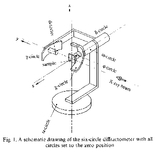
  -axis forms a right handed orthonganl system with the others. The figure shows the setup with all six angles and a diffrent lab frame from the paper Lohmeier1993 (
 ,
,  ,
,  ).
).
Rotations and Setting Angles
The rotation by  along the
  -axis leads to
  followed by the angles familiar from the four circle setup, i.e.
rotation by along the
followed by the angles familiar from the four circle setup, i.e.
rotation by along the  -axis leads to
  (-frame,
  ),
rotation by
),
rotation by  along the
  -axis leads to
  , and
rotation by along the
, and
rotation by along the  -axis leads to
  (-frame,
  )
The detector rotations start in with
rotation by
)
The detector rotations start in with
rotation by  along the -axis into
  , and
rotation by
, and
rotation by  along the
  -axis into
  .
Note that in the origanal paper is called
.
Note that in the origanal paper is called  .
After this introduction we will drop most times the indices at the axes and refer to the four circle lab frame.
.
After this introduction we will drop most times the indices at the axes and refer to the four circle lab frame.
| Angle | Axis4 | Axis6 | New Frame |
|---|---|---|---|
|
|
 |
|
|
|
 |
() |
|
|
 |
|
|
|
 |
() |
|
|
|
|
|
|
 |
|
Rotation matrcies
Rotation of a vector  along the
  -axis by the angle is discribed by the rotaion matrix
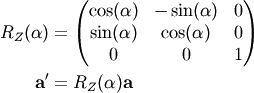
The back transformation is the transposed  or
or  , the back rotation. If the coordinate system is rotated by the angle , is the transformation.
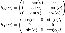
For completness the other two rotation matrices along the principle axes.
, the back rotation. If the coordinate system is rotated by the angle , is the transformation.
For completness the other two rotation matrices along the principle axes.
Calculation of  
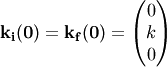
The initial and final (scattered) wavevectors are  ,
,  and have the same length
  (elastic scattering).
For all setting angels set to 0, and lay along the
(elastic scattering).
For all setting angels set to 0, and lay along the  -axis.
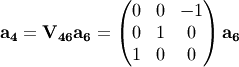
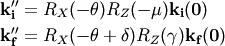
To get  , i.e. in
  , we have to apply the rotation matrix along by the angle
  and the rotation matrix along
  by the angle
  , because
  for all angles. To get
  we have to considered that
  for all angles, becuase the measured scattered X-rays hit directly the detector. In a similar sence we need rotations by
  along
along  and by
  along .
Now we get  in .
in .
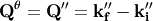
If we take the rotations by and into account we come to .
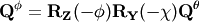
The last step is transforming from  to
to  and applying the inverse orientation matrix
  from e.g. Spec SIXC to get the
  -values.
Diffractometer Class
- class pyspec.diffractometer.Diffractometer(mode='sixc')
Diffractometer class
This class provides various functions to perform calculations to and from the sample and instrument frames
used lab frame: Z up, Y along X-ray beam, X = Y x Z; sample rotations: mu : along +Z -> S’ (mu-frame), theta : along +X’ -> S’’ (theta-frame), chi : along +Y’’ -> S’‘’ (chi-frame), phi : along +X’‘’ -> S’‘’’ (phi-frame); detector rotations: mu : along +Z -> S’ (mu-frame), delta : along +X’ -> S* (delta-frame), gamma : along +Z* -> S** (gamma-frame)
- getQCart()
Calculate (Qx, Qy, Qz) set in cartesian reciprocal space from (Qx, Qy, Qz) set in theta-frame
still under construction
- getQHKL()
Calc HKL values from (Qx, Qy, Qz) set in theta-frame with UB-matrix
QHKL = UB^-1 sixcToFourc^T QPhi
- getQPhi()
Calculate (Qx, Qy, Qz) set in phi-frame from (Qx, Qy, Qz) set in theta-frame
QPhi = rotZ(-phi) rotY(-chi) QTheta
- getQTheta()
Return transformed coordinates
- setAllAngles(angles, mode='deg')
Sets angles for calculation. Angles are expected in spec ‘sixc’ order: Delta Theta Chi Phi Mu Gamma
- setAngles(delta=None, theta=None, chi=None, phi=None, mu=None, gamma=None, mode='deg')
Set the angles for calculation
- setEnergy(energy)
Set the energy (in eV) for calculations
- setLambda(waveLen)
Set the wavelength (in Angstroms) for calculations
- setUbMatrix(UBmat)
Sets the UB matrix