Amplitude Modulation with an analog multiplier IC

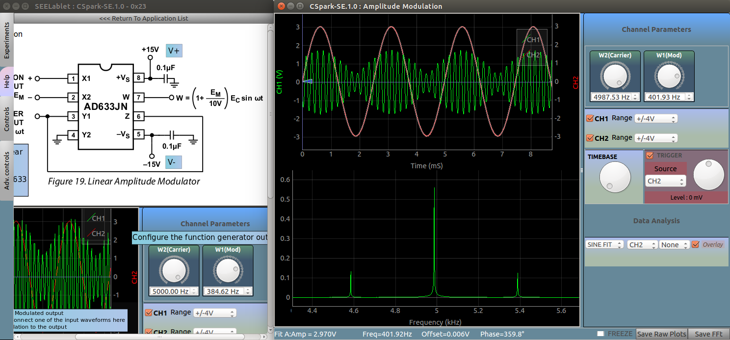
The AD9833 is a high bandwidth analog multiplier IC, and the circuit shown functions as a linear amplitude modulator.
W2 is chosen as the Carrier wave. Its amplitude is reduced by half using a 1k,1k potential divider before feeding it to the IC because the power supply taken from the SEELablet is inadequate for a 3V carrier wave.
If you choose to provide a +/-15Volts power supply externally, this voltage divider can be bypassed.
W1 is the modulation input. Use the amplitude control knob to study its effect on the output waveform.
CH1 monitors the modulated output .
CH2 can be connected to either the carrier, or the modulation wave in order to curve fit and study their relation to the modulation output .
The Second graph shows a fourier transform of the modulation output. The central peak corresponds to the carrier frequency,
and two sidebands are at a distance of W from the carrier, where W= frequency of the modulation input.
Screenshot

