Clamping Circuit using a diode

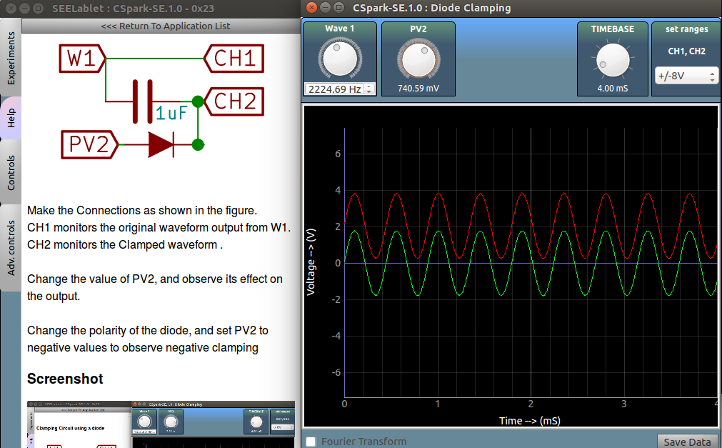
Make the Connections as shown in the figure.
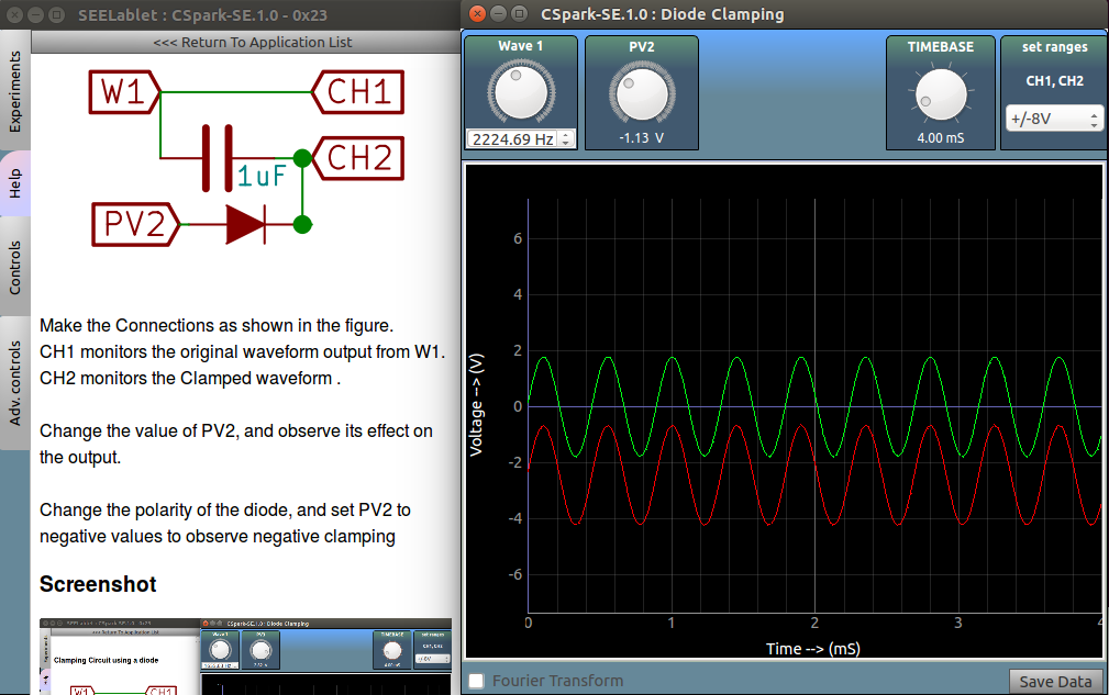
CH1 monitors the original waveform output from W1.
CH2 monitors the Clamped waveform .
Change the value of PV2, and observe its effect on the output.
Change the polarity of the diode, and set PV2 to negative values to observe negative clamping
Screenshot:positive clamping

Screenshot: negative clamping


