18. Gear Profile Theory
18.1. Transmission per adhesion
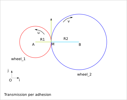
(O,i,j) orthonormal reference frame

wheel_1 rotation speed: u (radian/s)
wheel_2 rotation speed: v (radian/s)
speed of M, point of wheel_1:
V(M) = u*R1*j
speed of N, point of wheel_2:
V(N) = v*R2*j
Because of the adhesion of the wheel_1 and wheel_2 in M:
V(M).j = V(N).j
u*R1 = v*R2
v = u*R1/R2
18.1.1. Issue
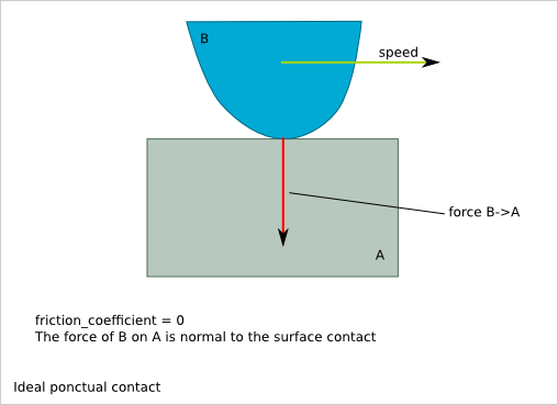
The maximal torque transmission is limited by the adhesion capacity.
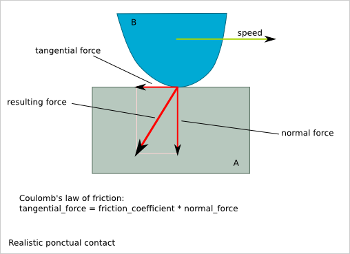
18.1.2. Idea
Create hollows and bums around the wheel to get a contact point force transmission.
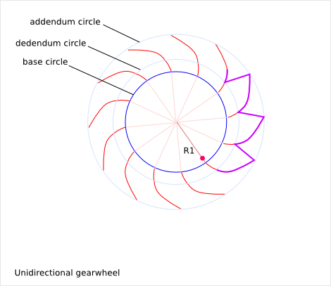
18.2. Transmission with teeth
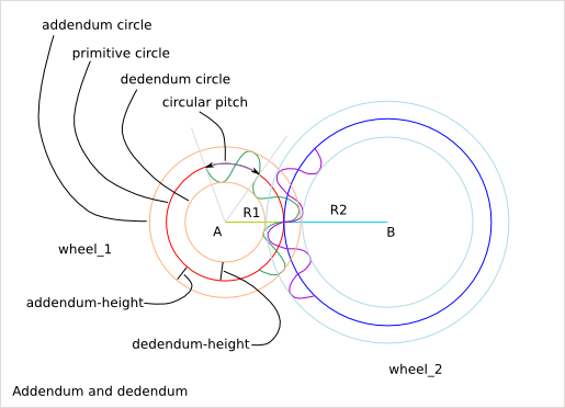
18.2.1. One wheel description
angular_pitch = 2*pi/tooth_nb
circular_pitch = angular_pitch * primitive radius
addendum_radius = primitive_radius + addendum_height
dedendum_radius = primitive_radius + dedendum_height
tooth_height = addendum_height + dedendum_height
18.2.2. Conditions for working gear
circular_pitch_1 = circular_pitch_2
addendum_height_1 < dedendum_height_2
addendum_height_2 < dedendum_height_1
transmission ratio = primitive_radius_1 / primitive_radius_2 = tooth_nb_1 / tooth_nb_2
Problematic: How to design the tooth-profile?
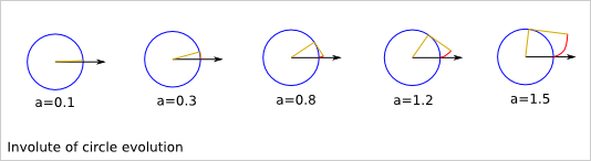
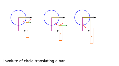
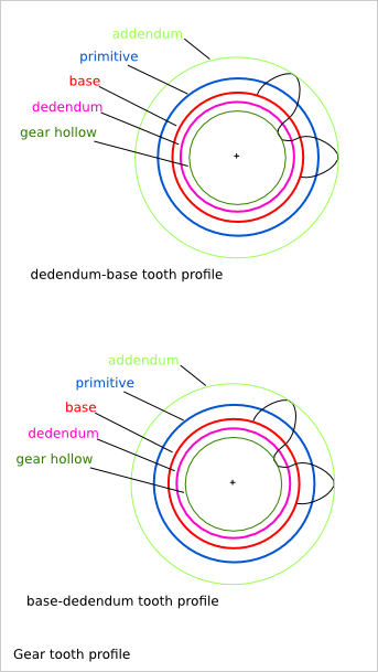
18.3. Tooth profile
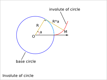
Cartesian equation:
Mx(a) = R*cos(a)+a*R*cos(a-pi/2)
My(a) = R*sin(a)+a*R*sin(a-pi/2)
Trigonometry formula remind:
cos(-x) = cos(x)
sin(-x) = -sin(x)
cos(pi/2-x) = sin(x)
sin(pi/2-x) = cos(x)
cos(a-pi/2)=cos(pi/2-a)=sin(a)
sin(a-pi/2)=-sin(pi/2-a)=-cos(a)
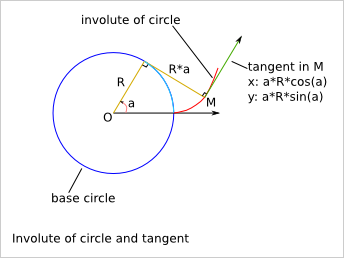
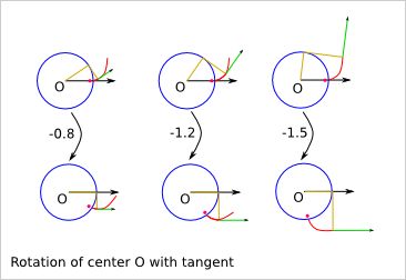
Tangent vector:
Mx'(a) = -R*sin(a)+R*cos(a-pi/2)-a*R*sin(a-pi/2) = -a*R*sin(a-pi/2) = a*R*cos(a)
My'(a) =  R*cos(a)+R*sin(a-pi/2)+a*R*cos(a-pi/2) =  a*R*cos(a-pi/2) = a*R*sin(a)
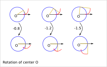
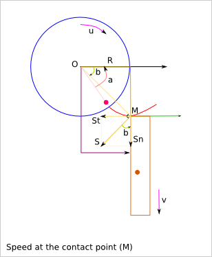
u: rotation speed of the wheel
v: linear speed of tha bar
u(t) = d/dt(a(t))

OM = sqrt(R² + (a*R)²) = R*sqrt(1+a²)

S = OM*u
Sn = S*cos(b)
St = S*sin(b)

Sn = u*R*sqrt(1+a²)*cos(b)
relation between a(t) and b(t)?
tan(b) = (a*R)/R = a
Sn = u*R*sqrt(1+tan²(b))*cos(b)
Trigonometry formula remind:
1+tan²(x) = (cos²(x)+sin²(x))/cos²(x) = 1/cos²(x)
So,:
v = Sn = u*R
v does not depend on the angle a!
St = u*R*sqrt(1+a²)*sin(b) = u*R*tan(b) = u*R*a
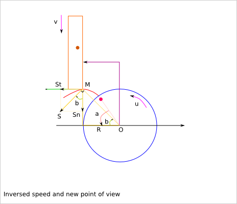
u: rotation speed of the wheel
v: linear speed of tha bar
u(t) = d/dt(a(t))

OM = sqrt(R² + (a*R)²) = R*sqrt(1+a²)

S = OM*u
Sn = S*cos(b)
St = S*sin(b)

v = Sn = u*R*sqrt(1+a²)*cos(b)
= u*R*sqrt(1+tan²(b))*cos(b) = u*R
v does not depend on the angle a!
St = u*R*sqrt(1+a²)*sin(b) = u*R*tan(b) = u*R*a
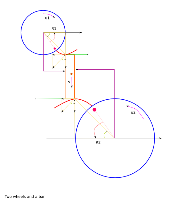
v = u1*R1 = u2*R2
So, u2 = u1*R1/R2
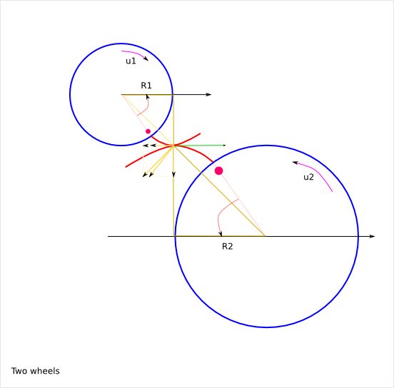
Sn1 = Sn2 because of the contact
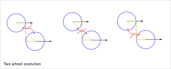
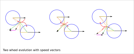
Friction between the two wheels:
Sf = St2 - St1 = u2*R2*a2 - u1*R1*a1
= u1*R1*(a2-a1)
But,
a1 = k1-u1*t
a2 = k2+u2*t
Sf = u1*R1*(k1-k2+(u1+u2)*t)
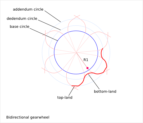
18.5. Gear rules
The base diameter of the two directions can be different
- The top-land and bottom-land are not critical part of the profile
The top-land can be a straight line. The bottom-land is usually a hollow to help the manufacturing.
The rotation ratio implies by the involutes-of-circles is:
base_radius_1 / base_radius_2
The rotation ratio implies by the teeth is:
tooth_nb_1 / tooth_nb_2
In order to get a continuous transmission without cough, we must ensure that:
base_radius_1 / base_radius_2 = tooth_nb_1 / tooth_nb_2
If you use two base circles for the positive rotation and the negative rotation, then:
base_radius_positive_1 / base_radius_positive_2 = tooth_nb_1 / tooth_nb_2
base_radius_negative_1 / base_radius_negative_2 = tooth_nb_1 / tooth_nb_2
The position of the positive involute of circle compare to the negative involute of circle is arbitrary and it is usually defined by the addendum-dedendum-ration on the primitive circle. Just make sure the top-land and bottom-land still exist (positive length). The addendum-dedendum-ration of the second wheel must be the complementary.
Do not mix-up the primitive circle and the base circle. The primitive circle helps defining the addendum and dedendum circles. The base circle defines the involutes of circle.We have the relation:
base_radius < primitive_radius
18.6. Torque transmission
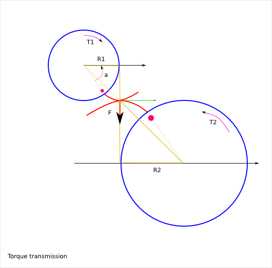
F = T1/R1 = T2/R2
T2 = T1*R2/R1
The transmitted torque T2 does not depend on the angle a!
18.7. Gearwheel position
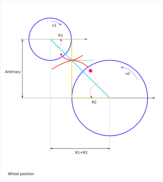
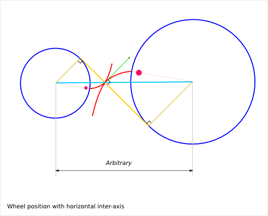
The rotation ration depends only on the two base circle diameters. It does not depend on the inter-axis length. The inter-axis length can be set arbitrary within a reasonable range (addendum and dedendum height constraints).