25. Epicyclic Gearing Design
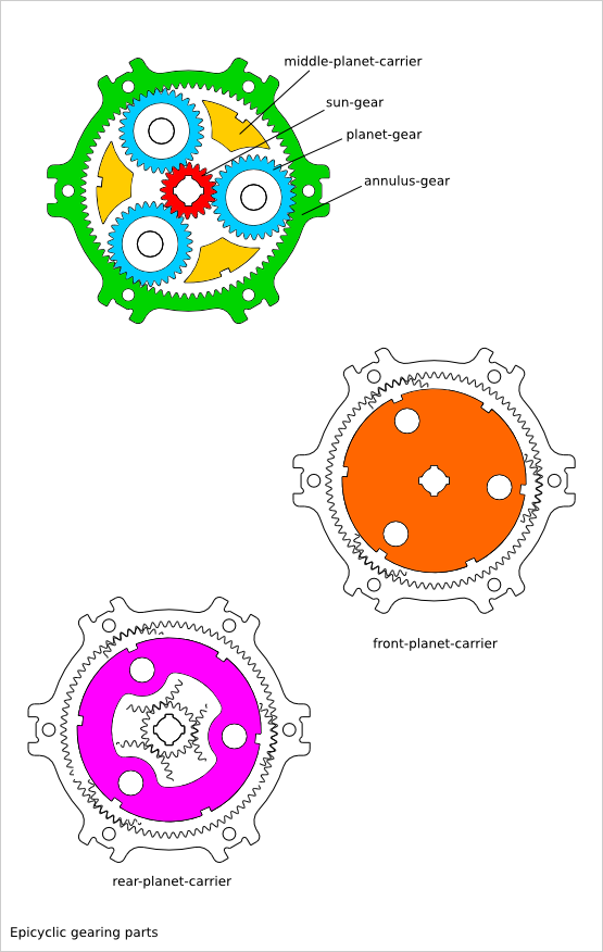
Ready-to-use parametric epicyclic-gearing design. The epicyclic gearing is a system made out of several parts:
- sun-gear
- planet-gear
- annulus-gear
- planet-carrier (rear, middle and front)
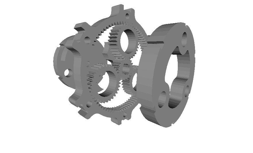
You can generate several configuration of epicyclic gearing system:
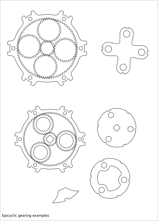
To get an overview of the possible epicyclic-gearing designs that can be generated by epicyclic_gearing(), run:
> python epicyclic_gearing.py --run_self_test
25.1. Epicyclic Gearing Parameter List
The parameter relative to the gearring are inherit from the Gearring Design.
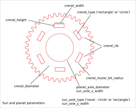
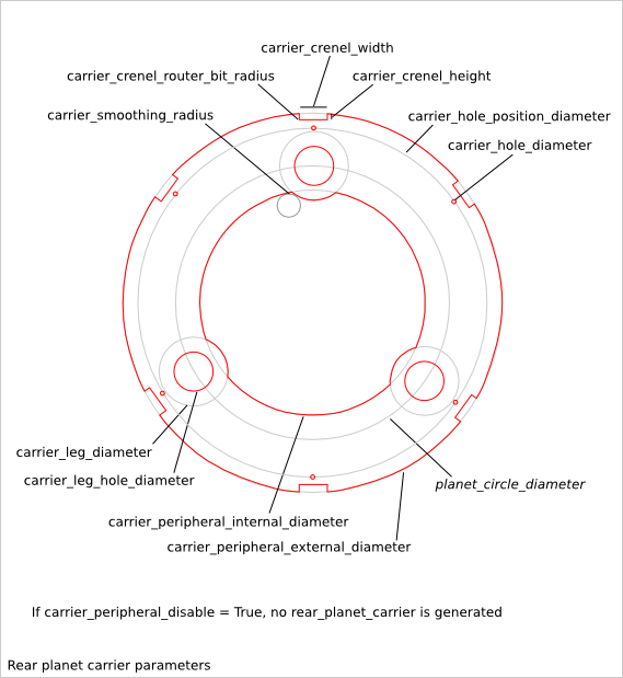
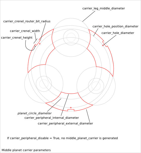
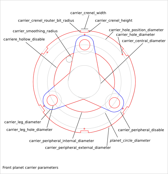
25.2. Epicyclic Gearring Parameter Dependency
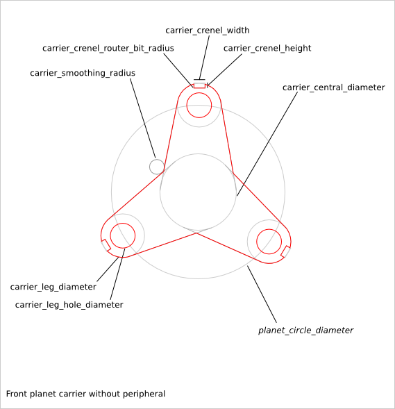
25.2.1. router_bit_radius
Six router_bit radius are defined: gear_router_bit_radius, sun_crenel_router_bit_radius, planet_crenel_router_bit_radius, carrier_crenel_router_bit_radius, carrier_smoothing_radius and cnc_router_bit_radius. Each set the router_bit radius for different areas except cnc_router_bit_radius that set the minimum value for the five other router_bit radius. If an other router_bit radius is smaller than cnc_router_bit_radius, it is set to cnc_router_bit_radius. So, we have the relations:
cnc_router_bit_radius < gear_router_bit_radius
cnc_router_bit_radius < sun_crenel_router_bit_radius
cnc_router_bit_radius < planet_crenel_router_bit_radius
cnc_router_bit_radius < carrier_crenel_router_bit_radius
cnc_router_bit_radius < carrier_smoothing_radius
If you leave carrier_smoothing_radius to 0.0, it will be changed automatically to a default larger value.
25.2.2. sun_gear_tooth_nb and planet_gear_tooth_nb
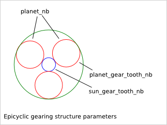
sun_gear_tooth_nb and planet_gear_tooth_nb set the number of teeth of the sun-gear and planet-gears. The number of teeth of the annulus-gear is set to:
annulus_gear_tooth_nb = sun_gear_tooth_nb + 2 * planet_gear_tooth_nb
To get a working epicyclic-gearing, the sum of sun_gear_tooth_nb and annulus_gear_tooth_nb must be divisible by the number of planet-gears:
(annulus_gear_tooth_nb + sun_gear_tooth_nb) % planet_nb = 0
equivalent to:
(2*(sun_gear_tooth_nb + planet_gear_tooth_nb)) % planet_nb = 0
The transmission ration is equal to:
sun_gear_tooth_nb/(sun_gear_tooth_nb + annulus_gear_tooth_nb)
25.2.3. planet_nb
planet_nb sets the number of planet-gears. If planet_nb is set to 0, the maximal number of planet-gears is chosen.
25.2.4. carrier_peripheral_disable
If carrier_peripheral_disable is True, no rear-planet-carrier and no middle-planet-carrier are generated. The front-planet-carrier has also an alternative design.
25.2.5. carrier_hollow_disable
If carrier_hollow_disable is True, hollows are created in the front-planet-carrier. This remove some material to get a lighter system. This option is available only when carrier_peripheral_disable is False.
25.2.6. carrier_crenel_height
carrier_crenel_height sets the height of the carrier-crenels. If carrier_crenel_height is set to 0, the carrier-crenel are not created. The number of carrier-crenels is 2*planet_nb.
25.2.7. planet_axle_diameter and carrier_leg_hole_diameter
planet_axle_diameter and carrier_leg_hole_diameter are both related to the diameters of the planet-gear axle. planet_axle_diameter sets the diameter of the axle of the planet-gears. carrier_leg_hole_diameter sets the diameter of the corresponding coaxial holes in the rear and front planet-carrier. Using two different values for these two parameters can be useful when you want to use a ball bearing system.
25.2.8. sun axle and carrier axle design
The sun axle design is defined with several parameters such as sun_axle_diameter, sun_crenel_diameter, sun_crenel_nb, sun_crenel_width, sun_crenel_height and sun_crenel_router_bit_radius. The design of the axle of the plant-carrier is copied from the sun axle design. So there is no parameters directly related to the planet-carrier axle design. Notice that in case of cascade epicyclic gearing, the planet-carrier of a stage intends to be jammed to the sun-gear of the next stage.
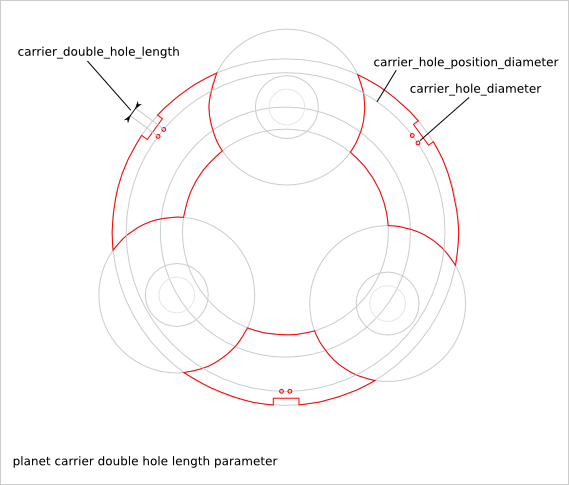
25.2.9. carrier_double_hole_length
The crenel-hole can is replaced by a double-crenel-hole when carrier_double_hole_length is set to a float bigger than zero. In this case, two holes are created with a distance of carrier_double_hole_length. Double-hole are useful to increase the stability of the planet-carrier.
25.2.10. top_lid parameters
Those parameters are inherit from Axle Lid Design
25.2.11. input and output gearwheels
The epicyclic-gearing design can generate the input and the output gearwheels. It is recommended to re-generate those gearwheels with the gearwheel.py script to get access to the complete Gearwheel Design parameter list.
25.3. Epicyclic Gearing Recommendations
25.3.1. For laser-cutter
The laser-cutter remove usually more material than the ideal line. This is because of the lase beam width. To get a well adjusted gear system without too much play, we need to compensate this excess of removed material. The parameter gear_skin_thickness lets you move the gear-profile-outline in order to compensate the laser beam width. Because the laser remove too much material, you should set gear_skin_thickness to a positive values (e.g: 0.75 mm).
If you set a quiet large value to gear_skin_thickness, it may happens that the gear-ring (a.k.a. annulus) can not be generated any more because its bottom-land is too small or even negative. In this case, there is a small workaround: modify slightly the lowest part of the dedendum of the gear-ring to make this gear-hollow feasible by using the parameter gearring_dedendum_to_hollow_pourcentage. For example, if gearring_dedendum_to_hollow_pourcentage is set to 10, 10% of the gear-ring dedendum is changed into the gear-hollow.
gear_skin_thickness does not compensate the height of the gear-teeth. If you think the laser-cutter make the gear-teeth too small, you can increase the value of the parameter gear_addendum_height_pourcentage. For example, if you set gear_addendum_height_pourcentage to 110, the theoretical (before laser-cutting) gear-tooth-addendum height is set to 1.1*gear_module.
25.3.2. For 3D printing
Usually 3D printed parts are a bit larger than the CAD design. This is because of the extruded wire width. This extra thickness can be compensated with a negative value sets to the parameter gear_skin_thickness.
If you set a too large negative value to gear_skin_thickness, the top the gear-tooth might not be designable anymore because the top-land will be negative. In this case, you can reduce the height of the gear-tooth addendum with the parameter gear_addendum_height_pourcentage. For example, if you set gear_addendum_height_pourcentage to 90, the theoretical (without the extra extruded wire width) gear-tooth-addendum height is set to 0.9*gear_module.
25.3.3. For CNC milling
With CNC, the biggest challenge is the size to the router-bit. cnc_router_bit_radius must be equal or bigger than the effective used router-bit radius. If gear_router_bit_radius is smaller than cnc_router_bit_radius, it is automatically sets to the value of cnc_router_bit_radius.
If gear_router_bit_radius is too large, it may happens that the gear-ring can not be generated anymore because the gear_router_bit_radius is too large compare to the gear-hollow width. In this case, there is a small workaround: modify slightly the lowest part of the dedendum of the gear-ring to make this gear-hollow feasible by using the parameter gearring_dedendum_to_hollow_pourcentage. For example, if gearring_dedendum_to_hollow_pourcentage is set to 10, 10% of the gear-ring dedendum is changed into the gear-hollow.